Land-vehicle Design
Bicycle Trailer

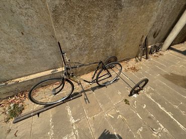
We are producing a lightweight attachment for a bicycle.
It could pull loads of about 60kg at reasonable speeds.
The attachment weighs about 10kg
(including wheel weight).
It has a width of 1m and adds 70cm to the length
(of the bicycle).
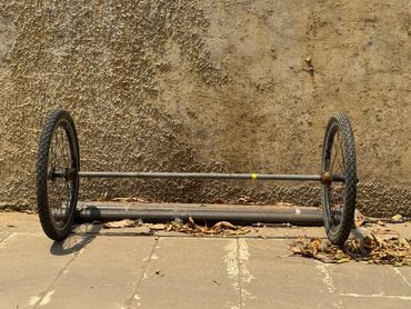
It has 2 axles,
a heavy, narrow axle for longitudinal stability and shock absorption.
and a lightweight, wider axle for lateral stability.
3 Design Considerations

Weight
Background
Load-carrying trikes are quite common in India.
A basic design has been in use, unmodified for more than a hundred years. The chassis of this tricycle is created by taking a roadster bike, removing the rear wheel and the rear part of the frame (behind the seat-post) and adding a heavy iron triangular frame that is connected to the bottom-bracket at the base of the bicycle frame and a heavy solid iron axle at the back.
The weight of such a trike is about 60kg. It can be used to pull loads of 500kg but at very slow speeds (3km per hour). This design has been used both for passenger transport (2 people) and for transporting loads.
Our weight target
We are designing a lightweight trailer starting with the same bicycle frame as was used in the trike design. It is a trailer attachment to a bicycle and not a trike. It weighs about 10kg.

Longitudinal Stability & Lateral Balance
Since the trailer is being designed for speed, we try to keep the weight of the load close to the center line of the trailer and we focus more on longitudinal stability than lateral balance.
Longitudinal Stability Axle
The primary axle of the trailer provides shock absorption and serves to stabilize the weight of the load behind the rider.
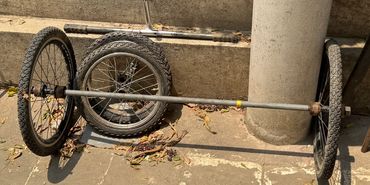
It is as narrow as possible and has 4 heavy-gauge 14" wheels in 2 pairs.
Lateral Balance Axle
The trailer also has a secondary axle which is wide and lightweight. It has a low pressure contact with the ground add serves to balance the load laterally. It also helps turn the trailer.

Shock Absorption
We use heavy duty wheels for the longitudinal stabilizer and lightweight wheels for the lateral balancer. Additional shock absorbers could be added.
Axles, Wheels, Structural Elements

Axles
The trailer consists of two axles.
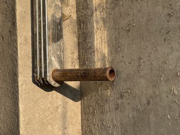
- A 1m wide forward axle with a 16in bicycle wheel at each end. This axle is designed to maintain lateral-stability. It is made with a 20mm outer diameter seamless steel pipe (2.5mm wall thickness) and weighs about 1.5kg.
- A 60cm wide rear axle with a pair of 14in bicycle wheels at each end. It is a load-bearing axle. It is made with a 16mm diameter solid steel rod and weighs about 1kg.

Wheels
We modify a stock 14in or 16in wheel in the following way:
- The spindle and ball-bearing housing are removed, leaving just the hub that binds the spokes.
- A sleeve is made using a 48.3mm outer diameter, 7.14mm wall thickness (schedule 160) seamless steel pipe section about 24mm long. This section is bored (about 12mm deep) to fit outside of the hub at one end and at the other end it is bored out (about 12mm deep) to fit a sealed ball-bearing. 2 such sleeves are made, one for either end of the hub. Each sleeve weighs about 50g.
- For the double wheel case, 3 ball-bearings are used for a pair of wheels. One goes between the 2 wheels and one each goes on the outsides of the wheel pair. The interconnecting sleeve is a slightly different design. It's actually 2 sleeves made the same way but only 18mm long. They are bored only 6mm deep on the ball-bearing side to fit half the ball-bearing. Their outer diameter is also reduced by 6mm. The 2 sleeves are fit into both sides of the ball bearing's outer casing. An additional outer sleeve of 36mm length and about 3mm remaining gauge encases these 2 sleeves. This design serves to align the wheel pair while providing an inter-wheel spacing of 36mm.

Structural Elements
All structural elements (for pulling, steering, strengthening and frame-building) are made using rectangular cross-section (40mm x 8mm), hollow (2mm gauge) steel beams. Weight is about 1.6kg/m.
These beams are strengthened at their attachment points with iron plate segments. A 4mm thick iron plate segment fits inside the beam and two 2mm thick plate segments sandwich it from the outside. The 3 plates and beam section are aligned, bored through with 2mm holes and riveted. (This keeps weight low while providing strength where needed).
A Possible Trailer Chassis

Assembling the Chassis
The 2 pulling beams are aligned and spaced about 70mm apart.
The 2 rear axle steering beams on are aligned with the rear axle line and placed close to the ends of the axle. Their non-axle ends are placed outward, away from the back of the trailer.
The 2 forward axle steering beams are aligned with the forward axle line, placed close to the ends of that axle and their non-axle ends are placed inward, towards the bicycle frame location.
The 2 axles are then passed through the 4 aligned holes in each case, then the locations of the beams are adjusted and fixed. Finally, the wheels are bolted in from the outside.

Attaching the Chassis to the Bicycle Frame
The chassis is attached to 2 load-bearing points in the bike frame:
The rear wheel spindle. This connects to the ground via the wheel spokes and rim, directly.
The seat-post. This connects to the ground at both front and back, wheel-ground interfaces through the bike frame. This is an indirect connection.
Possible Bicycle Frame Modifications

The handlebar, braking system and seat of the bicycle are redesigned to account for the additional load the bicycle will pull.
The frame of the bicycle is bolstered with 2 pairs of beams. (Structural description).This strengthens the frame and provides a mechanism to extend the trailer-frame forward.
The pulling beams are attached to the rear wheel spindle. The steering beams are attached to the seat-post.
Note: The chassis can also be attached to a specially designed pulling handle. This is useful in a scenario where a load is transported by road to a location and then pulled off-road to its final location manually. This makes the unloading process more efficient.
Trailer Frame Design

Base design -- Design Approach
Weight Distribution
The frame design promotes keeping the weight of the load, balanced along the center-line of the trailer. This helps reduce tyre-road friction, hence increasing speed. The base frame rests primarily on the center of the rear axle, on the sides of the lateral-stability axle and the seat-post of the bicycle.
Useable Length
It then has narrow forward extension from the seat-post to the handle.
The useable length of the trailer-frame is about 2m which is good for long, thin loads such as pipes or beams.

Reference Design
Slope
Carrier Shape
Carrier detachment and add-ons.
Packaging and Transportation

Packaging
Package Dimensions
The package should fit in the trunk of a sub-compact car
Package Layout
Layout 1
{
2 16" wheels without ball-bearings
4 ball bearings + 4 ball-bearing sleeves
4 14" wheels without ball-bearings
6 ball bearings + 8 sleeves
2 outer sleeves for inter-wheelpair alignment
}
Layout 2
{
60 cm solid steel 16 mm diameter axle (0.8 kg)
100 cm hollow steel tube 20 mm diameter axle (1.0 kg)
2 long pulling beams ( 1.0 m, 0.7 kg each )
2 secondary axle steering beams ( 1.0 m, 0.7 kg each )
2 primary axle steering beams ( 1.4 m, 1 kg each )
}

Transportation
Shipping via courier
Package dimensions and weight should conform to courier guideleines
Carry on luggage
Airline checked baggage rules
Car transportation
Package dimensions should fit in some refernce sub-compact
Image Gallery


