Bicycle rear-wheel-stabiliser
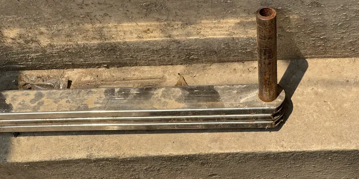
A steerable axle on paired wheels is attached via a lightweight metal frame to the rear-wheel spindle of a bicycle. It stabilises the bicycle at very slow speeds, adds rear-wheel shock absorption and also adds a load-bearing point behind the bicycle.
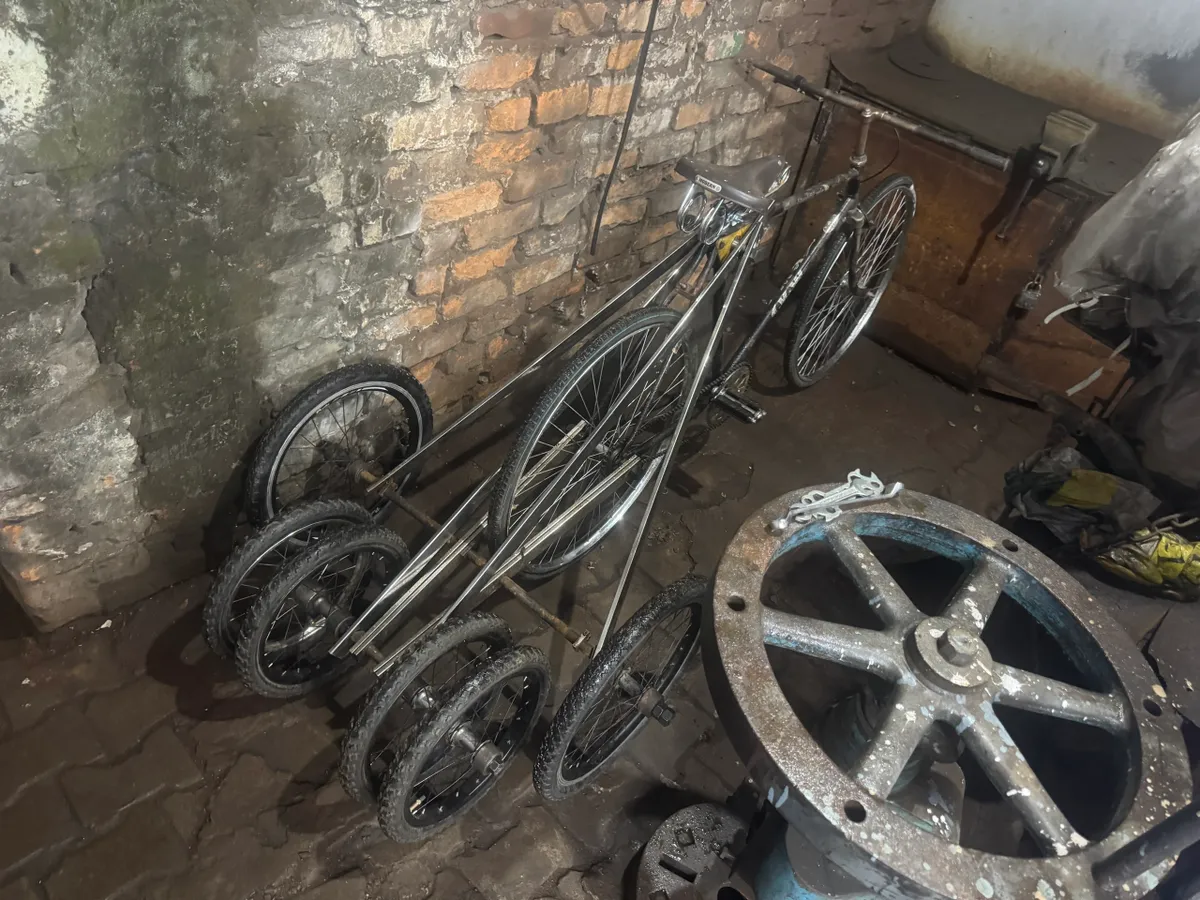
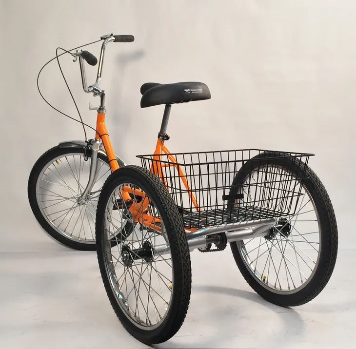
Note: The image above is the first produced prototype (31st Oct,2025). It does not turn easily, since it does not have any turning assist mechanism.
We designed a rear-wheel turning mechanism and functionally validated it on November 20th.
The axle is solid-steel (17mm diameter), 50cm wide.
It rolls on paired 14" wheels at both ends.
Specially designed sleeves and selected ball-bearing casings are used to pair the wheels.
Rectangular cross-section (40mm x 8mm), hollow (2mm gauge) steel beams are used for the frame.
A mechanical, chain-driven steering mechanism rotates the axle at half the rotation amount of the front wheel.
The mechanism consists of:
1) A freewheel that is screwed onto the head-tube of the bicycle
2) A hollow metal torque-transfer cylinder that is rigidly attached to the seat-tube.
A freewheel is screwed onto the top and to the bottom of this cylinder.
The head-tube (steering) free-wheel is connected to the torque transfer cyclinder's top free-wheel via a bicycle-chain.
When the bicycle handle is rotated, the head-tube rotates correspondingly which rotates the steering free-wheel. The connecting chain transfers this torque to the top free-wheel of the torque-transfer cylinder. This rotates the cylinder.
The bottom free-wheel rotates correspondingly to pull the axle from one side, while pushing from the other via 2 chain-driven rigid connectors (one for each side of the axle).
The stabiliser weighs about 6 kg, including tire and wheel weight, is about 50 cm wide and adds about 70 cm to the length of the host bicycle. It fits inside bicycle lanes and is easy to maneuver.
It's axle could be loaded up to 100 kg (220 lb) and move a speed of about 10 km/hr (6 mi/hr) in manual hauling.
It's component parts are:
- (14" rims + 16" tires) x 4
- (2 outer sleeves + 2 ball-bearings, 1 interconnecting sleeve + 1 ball-bearing) x 2
- 50 cm, 17mm solid-steel axle + (16mmx1mm nuts) x 2
- (((40mm x 8mm) cross-section, hollow (2mm gauge) steel beams of 1m length) x 2) x 2
- (Rear-wheel spindle to frame-tube connector + (20mmx1.5mm nuts) x 2) x 2
This rear-wheel-stabiliser could be used as a permanent attachment to a heavier bicycle (such as a 20kg roadster bicycle). It adds only a little more effort to ride the bicycle, does not reduce maneuverability in traffic, and improves riding comfort, while also serving a utilitarian function of carrying loads when needed. It could also be used in a battery-power assisted bicycle, since these are inherently heavier.
Find out more
The cargo-carrying axle is a heavy-gauge metal tube (21.3mm OD, schedule 160, seamless), that rolls on single 16" wheels.
It can be attached to the stabiliser's frame in a similar way as the stabiliser's axle, at a point between the rear-wheel spindles and the stabiliser's axle.
A cargo-carrying frame is supported via vertical steel-tubes at the 2 extremities of this cargo axle.
The frame can additionally be supported (by vertical steel tubes) at the rear-axle center of the trailer-chassis and attached to the seat-post corner of the bicycle-frame.
(*) Cargo axle + cargo-carrrying frame could typically weigh 10kg.
Design considerations
We discuss the design considerations used in the design of this bicyle-stabiliser.

Background
Load-carrying trikes are quite common in India.
A basic design (shown in picture) has been in use, unmodified for more than a hundred years.
The chassis of this tricycle is created by taking a roadster bike, removing the rear wheel and the rear part of the frame (the seat-stay and the chain-stay) and adding a heavy iron triangular frame that is connected to the bottom-bracket at the base of the bicycle frame and rolls on a heavy solid-iron axle at the back.
A cargo-carrying frame or passenger-carrying frame is built on top of this triangular iron frame.
The weight of such a trike is about 60kg.
It can be used to pull loads of 500kg but at very slow speeds (3km per hour).
This design has been used both for passenger transport (2 people) and for transporting loads.
Our weight-target
We targeted the design of a lightweight trailer starting with the same bicycle frame as was used in the trike design.
It would be a trailer attachment to a bicycle and not a trike.
It would weighs about 14kg (unladen).
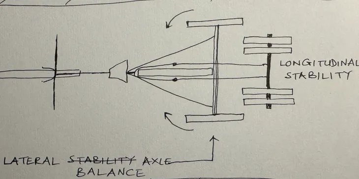
Since the trailer was being designed for speed, we tried to keep the weight of the load close to the center line of the trailer and we focussed more on longitudinal stability than lateral balance.
Longitudinal Stability Axle
The primary axle of the trailer would provide shock absorption and serves to stabilize the weight of the load behind the rider.
It would be as narrow as possible and have 4 heavy-gauge 14" wheels in 2 pairs.
Lateral Balance Axle
When a cargo-carrying frame and axle would be attached to the trailer-chassis, the cargo-carrying axle which would be wide and lightweight, would have a low pressure contact with the ground and serves to balance the load laterally.
We planned to use heavy duty wheels for the longitudinal stabilizer and lightweight wheels for the lateral balancer.
Additional shock-absorbers could also be attached to the axles.

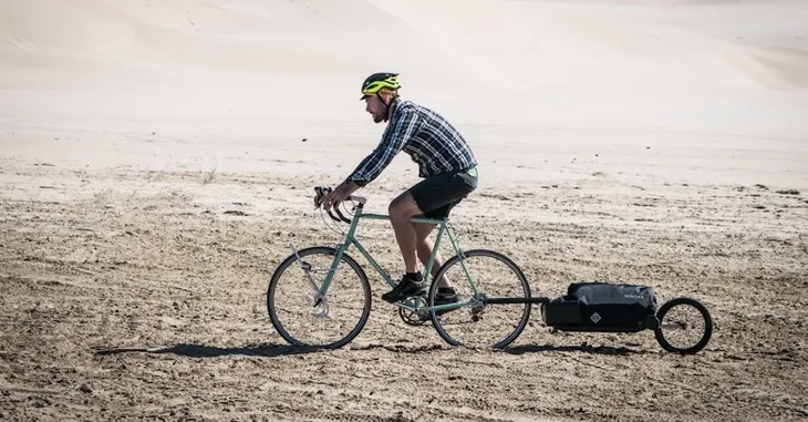
A modern commercial trike design (shown in the picture)
removes the rear-wheel and replaces it with a 2-wheel axle at the same location.
Hence, it has the riding characteristics of a bicycle and the additional stability and load-carrying capacity of a tricycle.
We targeted a bicycle-attachment type design with similar ruggedness and durability characteristics.
Part Descriptions
This section describes the design of the parts of the stabiliser, such as the axles and structural elements and the wheels, wheel-bearings and sleeves.
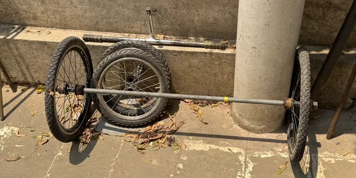
The trailer consists of two axles.
-
A 88 cm wide forward axle with a 16in bicycle wheel at each end.
This axle is designed to maintain lateral-stability.
It is made with a 20mm outer diameter seamless steel pipe (2.5mm wall thickness) and weighs about 1.5kg.
-
A 50 cm wide rear axle with a pair of 14in bicycle wheels at each end. It is a load-bearing axle.
It is made with a 16mm diameter solid steel rod and weighs about 1kg.
All structural elements (for pulling, steering, strengthening and frame-building) are made using rectangular cross-section (40mm x 8mm), hollow (2mm gauge) steel beams.
Weight is about 1.6kg/m.
These beams are strengthened at their attachment points with iron plate segments.
A 4mm thick iron plate segment fits inside the beam and two 2mm thick plate segments sandwich it from the outside.
The 3 plates and beam section are aligned, bored through with 2mm holes and riveted.
(This keeps weight low while providing strength where needed).
We bore the outer side of the sleeve to a 40mm diameter with a 12mm depth.
A 6203 bearing (40mm x 17mm x 12mm) slots into this bore.
The 17mm axle fits inside this bearing.
The total width of this sleeve is (12+12) 24mm.
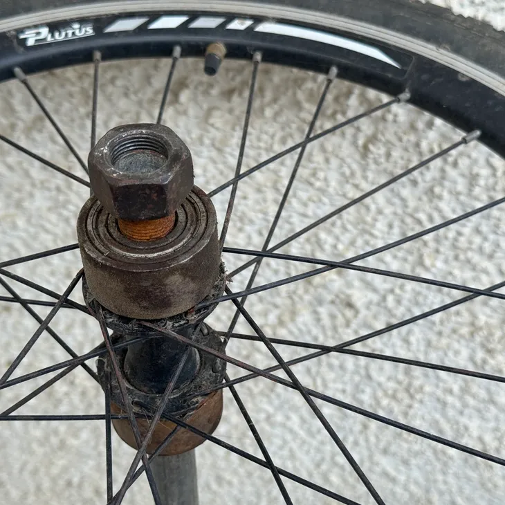
We also use a bearing between wheels for the wheel-pair.
Since this bearing fits between wheels and we want to minimize spacing between the wheels in the pair,
we only bore the sleeve to a 6mm depth on the bearing side (instead of 12mm).
The bearing slots halfway into one wheel's sleeve and halfway into the other wheel's sleeve.
These sleeves are therefore (12+6) 18mm wide.
We remove 2mm of material from the outside of both these sleeves, for an OD of 44.3 mm.
We create an addition sleeve (36mm wide) that is bored to 44.3mm.
This sleeve serves to align the 2 wheel-hub sleeves and hence the wheel-pair.
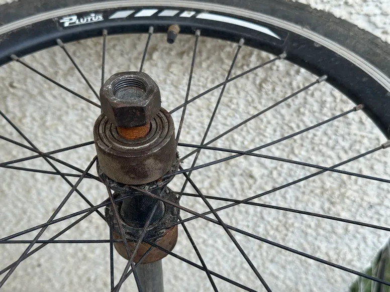
We take a stock bicycle wheel,
and remove the ball-bearing and inner ball-bearing holder attachments from the wheel-hub.
We add 1mm threads to both outer-extensions of the hub.
The OD of these extensions is about 35mm.
We use a 48.3mm OD seamless pipe (schedule 160) with a wall-thickness of 7.14mm (ID 34.02mm) to create sleeves.
We create a sleeve with an inner diameter of 35mm on one side.
We add 1mm threads to the inside of the sleeve on this side for 12mm.
This side of the sleeve is screwed into the outer-extension of the hub.
On the other side, it is bored depending on its usage.
The bearing used in this case is 6004 (20mm x 42mm x 12mm).
A pair of single sided sleeves is created for each wheel in this case.
Review of existing bicycle-trailer designs
This section reviews bicycle-trailers designs.
Several designs exist for very lightweight non-motorised or motorised trailers.
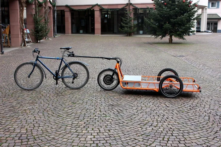
The most popular design of cargo-carrying bicycle-trailers is by Carla Cargo.
They can carry a weight of upto 200 kg and have a special brake design for the trailer that prevents it from running into the bicycle -- overrun brakes.
They are typically configured with a DC motor powering the trailer.
Worksmancycles has been producing commercial tricycle designs for several decades.
They are still typically non-motorised.